
In Part 1, we outlined the operational challenges facing the process industries and their answer: re-architecting the operational data infrastructure. In Part 2, we’ll focus on existing performance optimization architectures, the role of Large Language Models (LLMs) within the process, the OE performance optimization framework, and a real-world example for implementation.
Existing Performance Optimization Architectures
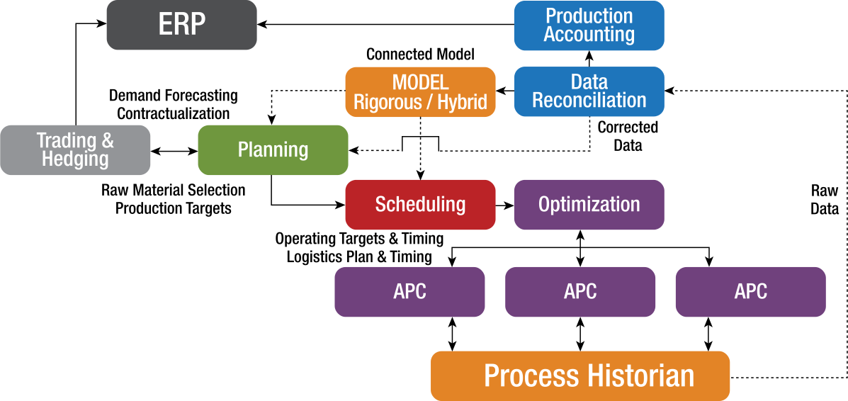
Figure 1 – Standard Performance Optimization Architecture
Above, I’ve outlined the standard performance optimization architecture for application in refining and petrochemicals, whose interfaces and control applications feature well-developed APIs that have long proven reliable. In this model, each application has its own operating time frame, ranging from real-time to daily, weekly, and monthly horizons.
If an engineer wanted to query the system to analyze enterprise-wide performance, coordinating a system like this would require significant human effort, and diagnosing issues is time-consuming; it doesn’t update automatically when something in the lower part of the system changes.
It is not simply a matter of layering a Large Language Model (LLM) on top of the applications to query them. LLMs are trained on massive amounts of text data that uses deep‑learning—specifically transformer neural networks—to understand, generate, and manipulate human language because they are contextual reasoners, not signal processors. At its core, an LLM predicts the next token in a sequence, but at scale, this enables far more complex behaviors such as reasoning, summarization, translation, coding, and dialogue.
OE-Centric Performance Optimization Architecture
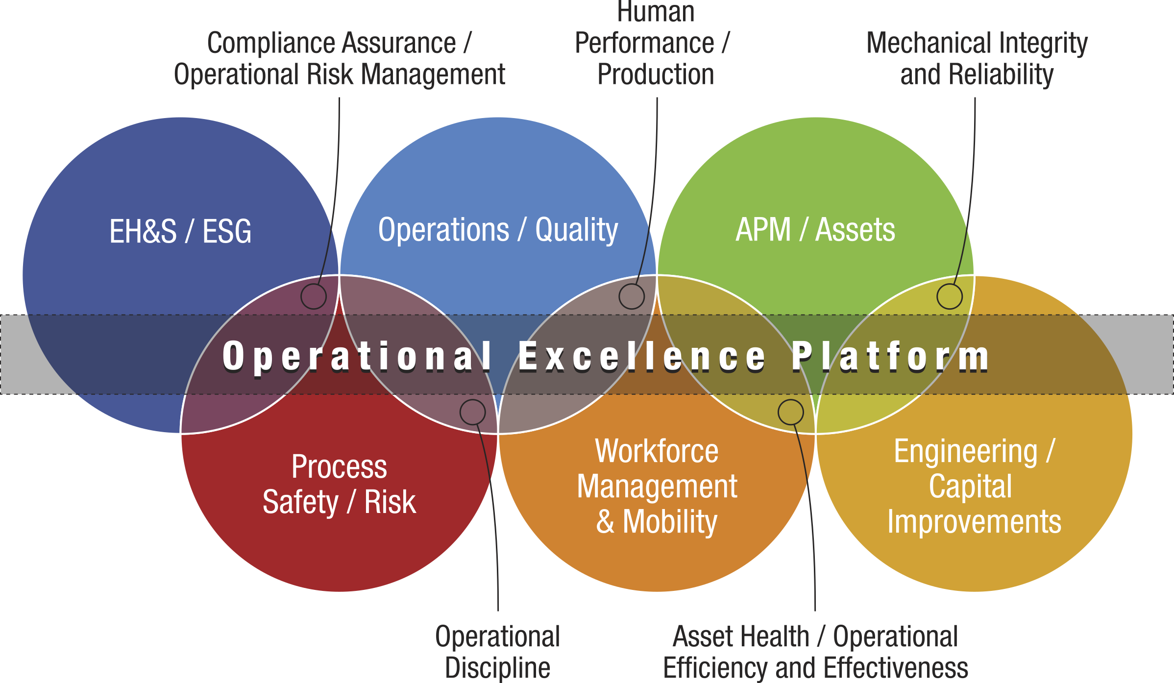
Figure 2 – Operational Sustainability® OE-Centric Performance Optimization Model
Industry continues to seek enhanced financial performance by seeking optimal performance without incurring enterprise losses, while operating plants within their risk appetites (not putting their license to operate at stake). Companies need to break down silos, or functions, around departments, culture, policies and procedures, and data management to achieve and maintain OE.
If we focus on one function—APM / Assets, for example—we would find multiple applications that require some form of connectivity and thus, relationships, including:
- Process historian for real-time time series data and calculations
- Predictive maintenance applications
- Enterprise asset management system for planning, scheduling, and tracking work orders
- Inventory management system to store spare parts and equipment
- Procurement system for acquiring equipment, parts, and materials
- Standalone asset integrity and risk assessment tools
As observed in Figure 2, each function interacts with other functions in one way or another, meaning their workflows span multiple systems. This means system integration and interoperability—defined as interconnected work processes that leverage a single unified architecture to enable proper interactions in the most efficient and effective way to achieve OE—are necessary to drive efficient, effective execution and provide visibility into current operations.
So, how do we build these multi-dimensional relationships? Let’s look at a real-world example.
Real World Example: Reliability Incident Investigation
Imagine a loss of containment occurs at a refinery unit. An investigation is launched. The control system identifies a problem with a piece of equipment—known to the DCS and historian as Pump-101A, to the maintenance system as P-101-Alpha, and to the reliability system as TX-9982.
With only syntactic interoperability, the process halts. A human must manually verify that these three strings refer to the same physical object. Without semantic interoperability, you cannot automatically trigger a maintenance work order or a reliability review based on the incident findings.
Contextually, the reliability system identifies the root cause of failure as seal fatigue due to the pump operating at the high end of the pump curve, normally requiring a Reliability Centered Maintenance (RCM) review, while the asset strategy system categorizes failure modes by ISO 14224 standards.
Syntactic interoperability allows the reliability system’s findings to move, but the asset strategy system doesn't know that the finding maps to the specific failure-mode code, 1.2.4 - Mechanical Wear. Because the systems don't share a common taxonomy, let alone an ontology, it's impossible to automate updates to the Asset Strategy.
A syntactic system also creates an orchestration barrier. If an incident investigation identifies a high-risk systemic issue, it should automatically trigger a Management of Change (MOC), which leads to an RCM review or Safety Instrumented System (SIS) validation. However, syntactic systems are reactive, storing data without understanding process states. Without semantic interoperability, systems only recognize a high-risk status as a data label, not a command to initiate workflows in adjacent software modules or applications.
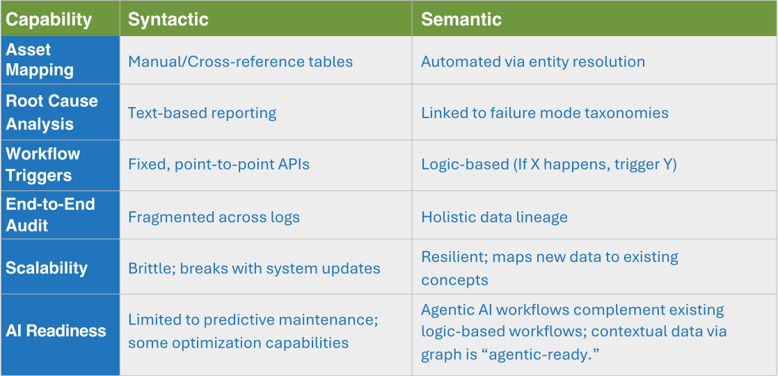
What this real-world example demonstrates is that syntactic systems create three significant areas of concern:
- The Human-in-the-Loop Tax – Humans must act as middleware because systems don’t share meaning. A subject matter expert with access to relational data systems and reporting tools must read the investigation report, log in to the MOC system, retype the asset ID, and summarize the findings. This introduces latency and data entry errors.
- Lack of Dynamic Lineage – In a syntactic environment, you can see that an incident happened and a change was made. However, you cannot easily trace the logic backward, whereas a semantic model (graph) maintains this lineage automatically.
- Data Decay – Industrial data is dynamic. If a pump is replaced with a different model during an MOC, a syntactically linked warehouse will often contain conflicting data (i.e., the old asset ID in the Incident log and the new ID in the Maintenance log). A semantic model uses a knowledge graph to link both records to a single entity, ensuring that the work process always acts on the most current version of the truth. A knowledge graph is a knowledge base that uses a graph-structured data model or topology to represent and operate on data.